A few years back I was helping review a material list for a gas transmission project — not a massive cross-country line, but a mid-size lateral feeding into a distribution network. One of the first things I noticed when I opened the pipe schedule was that the line wasn’t specified uniformly. The bulk of the straight runs were calling out large-diameter spiral welded pipe, but at every elbow cluster, every valve station, and the first several hundred meters coming off the compressor station, the spec switched to seamless.
The project engineer I was working with at the time had seen this before. He said something that stuck: “The pipe type follows the stress map. You’re not building one pipeline — you’re building several, and they just happen to connect.”
That framing helped me understand something I’d been vague on before: why seamless and welded pipe coexist in the same line, and why mixing them isn’t a compromise — it’s the correct engineering answer.
What Makes Seamless Different
Seamless pipe starts as a solid billet of steel, pierced and rolled into a tube without any longitudinal joint. There’s no weld seam, which means there’s no weld zone — no heat-affected area, no potential discontinuity running the length of the pipe that could be a stress concentration point.
That matters most in situations where the pipe is subject to complex or cyclically varying loads. Near bends and elbows, the flow changes direction and the pipe wall carries bending stress on top of the internal pressure load. At compressor or pump discharge points, the pipe is handling the highest system pressure, often with some pulsation added. In these areas, the absence of a seam isn’t a quality distinction in some abstract sense — it’s a specific structural advantage that the designer is relying on when they set the wall thickness and the allowable stress.
For oil and gas pipelines designed to standards like API 5L, the joint factor applied to a seamless pipe is 1.0. That means the pipe’s rated pressure capacity is calculated using the full material strength. Welded pipe — depending on the weld type and inspection level — carries a joint efficiency factor below 1.0 in some design codes, which reduces the allowable working pressure at a given wall thickness. In high-stress sections, that difference closes off the option of using welded pipe without going to a heavier wall, which may not be practical at the required diameter.
Where Welded Pipe Makes More Sense
The straight sections of a long-distance pipeline are a different environment. The load on the pipe in a straight, buried run is dominated by internal pressure, with ground movement and thermal cycling as secondary considerations. These are well-characterized loads that large-diameter welded pipe is specifically designed to handle.
ERW pipe — electric resistance welded — is produced by forming flat-rolled coil into a tube and welding the seam longitudinally using resistance heating. The result is consistent, inspectable, and manufactured to tight dimensional tolerances. For sizes up to about NPS 24, ERW is the workhorse of pipeline construction.
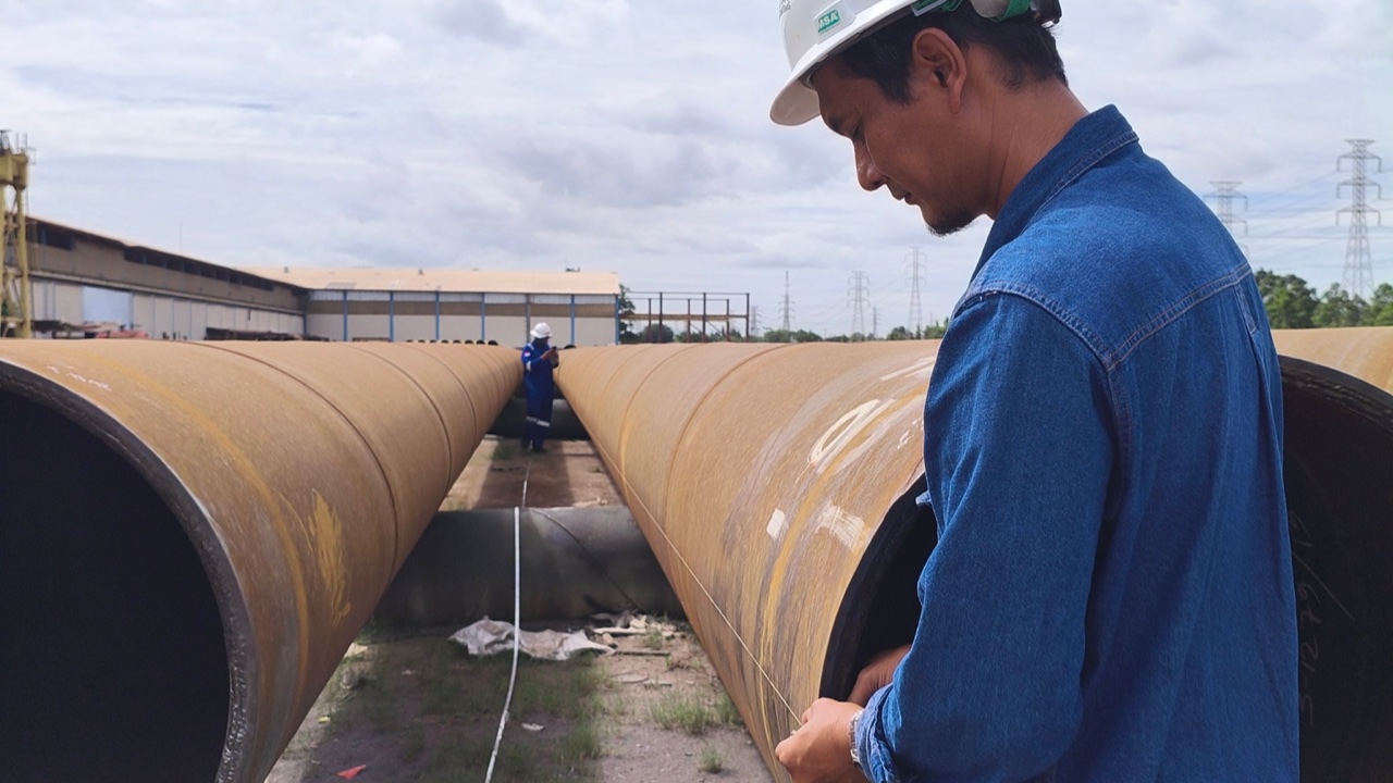
For very large diameters — NPS 24 and above — LSAW (longitudinally submerged arc welded) or SSAW (spirally submerged arc welded) pipe comes into play. SSAW in particular allows very large diameter pipe to be produced from standard-width coil by winding it at an angle and welding the spiral seam. This makes it economical for large-bore transmission lines where the economics of raw material handling would make seamless impractical regardless of the application.
The cost difference between seamless and large-diameter welded pipe is significant. For a straight run of several kilometers at NPS 20 or larger, specifying seamless would increase material cost substantially without providing any engineering benefit over properly inspected welded pipe at the same wall thickness.
The Transition Point
On a real project, the transition between pipe types is documented on the line list and reflected in the material take-off. The question of where exactly to make the change — how far from an elbow, how many pipe diameters downstream of a valve, how the transition is handled at the weld joint between two pipe types — gets worked out during the detailed engineering phase.
There are no absolute rules that apply universally; the answer depends on the operating pressure, the design code, the diameter, and the specific stress analysis for that section of line. What’s consistent across projects is the logic: seamless where the stress state is complex or where the joint efficiency factor would otherwise force a heavier wall; welded for the long runs where the loads are well-behaved and the economics of large-diameter production favor it.
When I was looking at procurement options for that gas lateral project, we ended up working with a supplier that could cover both pipe types from a single source. That mattered practically — it simplified the material certification tracking and the inspection requirements, since you weren’t coordinating between two different mills with two different production schedules. The steel pipe solutions from UNIACERO we evaluated at that stage covered both seamless and welded categories under API 5L, which made the comparison straightforward when we were splitting the line list into seamless and ERW sections.
What This Means for the Procurement Side
For anyone involved in buying pipe for a mixed-spec line, the key thing to get right early is the joint factor documentation. The design engineer needs to specify not just the pipe schedule and grade, but the applicable joint efficiency, the required inspection level, and any additional NDE requirements for the welded sections. These feed directly into the mill certification requirements, and getting them wrong means either over-specifying (and overpaying) or accepting pipe that doesn’t meet the design intent.
The other thing worth checking is dimensional compatibility at the transition welds. Seamless and welded pipe of the same nominal size and schedule should have matching outside diameters, but wall thickness tolerances differ between production methods, and the actual wall at the weld joint needs to be within the tolerance allowed by the applicable welding code for that joint to be acceptable.
None of this is complicated once you understand why the line is specified the way it is. The pipe type follows the stress map. The rest is documentation and inspection.